Laser cutting guidelines🔗︎
Discover all laser cutting guidelines here. By following the guidelines, the laser cutting process will run better.
General submissons specifications and guidelines
It is important, that the files you upload comply with our general guidelines and specifications. This will prevent error messages or a delivered product not meeting your expectations.
Minimum and maximum product dimensions🔗︎
There are limitations to the dimensions of the products we can produce. The minimum dimensions to keep the product manageable in the production process. The maximum dimensions arise because we are limited by the machines we use and the materials we purchase.
| Sheet thickness | Minimum dimensions | Maximum dimensions |
|---|---|---|
| 1 mm | 15 x 15 mm | 2980 x 1480 mm |
| 1,5 mm | 15 x 15 mm | 2980 x 1480 mm |
| 2 mm | 15 x 15 mm | 2980 x 1480 mm |
| 3 mm | 15 x 15 mm | 2980 x 1480 mm |
| 4 mm | 15 x 15 mm | 2980 x 1480 mm |
| 5 mm | 15 x 15 mm | 2980 x 1480 mm |
| 6 mm | 18 x 18 mm | 2980 x 1480 mm |
| 8 mm | 24 x 24 mm | 2980 x 1480 mm |
| 10 mm | 30 x 30 mm | 2980 x 1480 mm |
| 12 mm | 36 x 36 mm | 2976 x 1476 mm |
| 15 mm | 45 x 45 mm | 2970 x 1470 mm |
| 20 mm | 60 x 60 mm | 2960 x 1460 mm |
Minimum hole diameter🔗︎
f a hole is too small to cut, we will warn you about this and the hole will automatically be replaced with a mark which you can use to drill the hole anyway. In the table below you can see what the minimum hole diameters are, this depends on the chosen material and thickness.
| Sheet thickness | Steel | Stainless | Aluminium |
|---|---|---|---|
| 1 mm | 0,5 mm | 0,5 mm | 1 mm |
| 1,5 mm | 0,75 mm | 0,75 mm | 1,25 mm |
| 2 mm | 1 mm | 1 mm | 1,5 mm |
| 3 mm | 1,5 mm | 1,5 mm | 2 mm |
| 4 mm | 2 mm | 2 mm | 2,4 mm |
| 5 mm | 2,4 mm | 2,5 mm | 3,3 mm |
| 6 mm | 3 mm | 3 mm | 3,5 mm |
| 8 mm | 4 mm | 3,3 mm | 5 mm |
| 10 mm | 5 mm | 4,2 mm | |
| 12 mm | 6 mm | 6 mm | |
| 15 mm | 10 mm | 6,5 mm | |
| 20 mm | 14 mm |
Minimum slot width🔗︎
Minimum slot width is equal to minimum hole diameter. Check the table above for this.
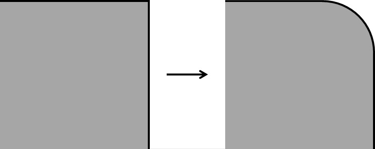
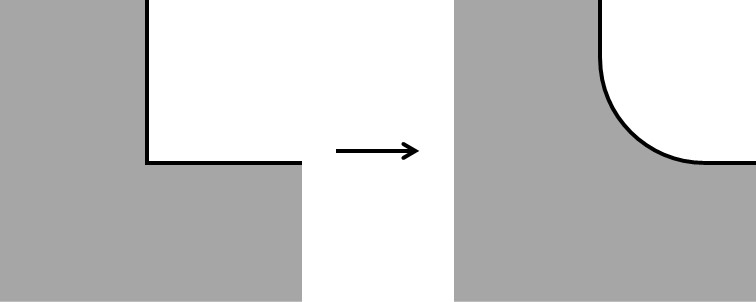
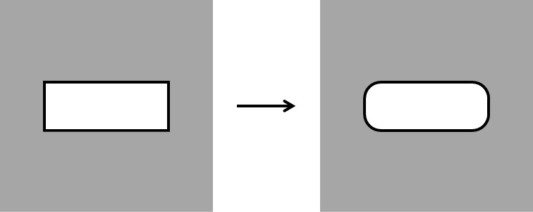
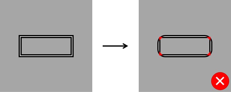
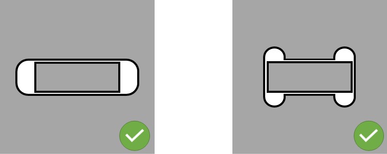
Corner rounding🔗︎
To optimize the cutting process and ensure cutting quality, all cutting contours are rounded. Take this into consideration in your design. The table below shows the radius used for rounding per material type and sheet thickness.
| Sheet thickness | Steel | Stainless | Aluminium |
|---|---|---|---|
| 1 mm | 0,5 mm | 0,5 mm | 0,5 mm |
| 1,5 mm | 0,5 mm | 0,5 mm | 0,5 mm |
| 2 mm | 0,5 mm | 0,5 mm | 0,5 mm |
| 3 mm | 0,5 mm | 0,5 mm | 0,5 mm |
| 4 mm | 0,5 mm | 0,5 mm | 1 mm |
| 5 mm | 1 mm | 1 mm | 1 mm |
| 6 mm | 1 mm | 1 mm | 1 mm |
| 8 mm | 1 mm | 1 mm | 1 mm |
| 10 mm | 1 mm | 1 mm | |
| 12 mm | 1 mm | 1 mm | |
| 15 mm | 2 mm | 1,5 mm | |
| 20 mm | 3 mm |
See below some drawings that clarify the corner rounding:
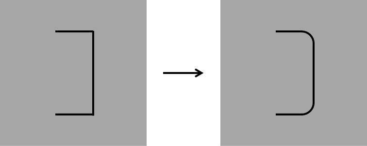
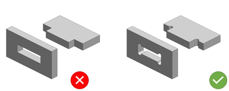
Interlocking connections🔗︎
For interlocking connections, keep in mind that problems can arise due to the corner rounding:
You can avoid these problems by making the lock longer or angling it out (a "dog bone").
Order part mirrored / rotated🔗︎
If you want to mirror/rotate flat parts (2D), please use the DXF file format. We recognise the top/bottom of a plate in a DXF file. This prevents the end result from being incorrectly mirrored. The view in the DXF is always the top side of the plate.
Text and logo🔗︎
Would you like to have text and/or a logo cut out? Keep in mind that the inner parts fall out of the plate. Connect the inner parts with bridges as shown in the image below. The bridges should have a minimum dimension of 0.5 x the thickness of the plate.
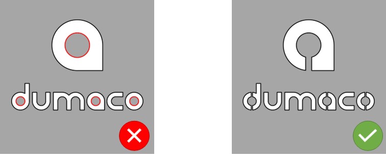
cut out text, number or logo
If you want to cut a text, number or logo on a flat part (2D), please use the DXF file format. In a DXF file we recognize the top/bottom of a plate.
Fonts🔗︎
There are special fonts that have been made suitable for laser cutting. Here are some examples:
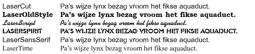
Fonts for laser cutting
Fonts for laser cutting can be downloaded here.
Engraving🔗︎
In addition to cutting, we can also engrave with our laser cutting machines: making a visible mark on the top of the plate. It is a technical engraving in the form of a thin line; we do not turn it into a work of art. Deep black engraving or flat engraving is not possible.
You can actively use the ability to engrave to facilitate follow-up operations. Examples include:
- Indicating positions of parts for the welder and/or assembly.
- For parts that are difficult to edge (or where no stop is possible), it can be useful to engrave the bending line.
- For holes that must be countersunk, it is useful to engrave the outside diameter so that it is immediately clear which hole and how deep it must be countersunk (we do this automatically from 3D).
- If chamfers need to be made for welding thicker material, you can indicate the location and width with an engraving (we do this automatically from 3D).
Points of interest:
- Engraving is recognized automatically:
- in 2D by a different layer and/or color
- in 3D by a blind hole, bevel or countersink
- Engraving is only possible on the top side.
- Engraving of foiled and/or polished material is not possible.
Engraving margin at outer contour
The engraving indicated is automatically corrected in the Dumaco Portal. From the outer contour, 1mm is left free. This is not engraved because of the production process.
Engraving part numbers🔗︎
Of course, it is also possible to engrave a part number or a (simple) logo. Please indicate this in your files.
Engravings
Please note that engravings are not always visible, due to post-processing e.g. edge breaking, sanding, blasting or coating.
Check out our latest updates and newest features of the Dumaco Portal.